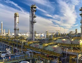
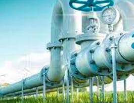
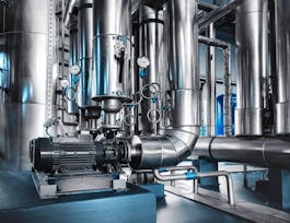
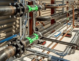
This particular course entitled “Pipe Material Specification” under the specialization entitled “Design of Industrial Piping Systems” is mainly aimed at piping system design aspects. The major differences between tube and pipe should be known to the designer first. The right selection of the straight pipe for a given process requirement is entirely based on the sound knowledge of the designer on pipe manufacturing techniques, pipe ends, pipe materials, and ASME B31 pressure piping series. Designers should be capable of determining the pipe wall thickness for the internal pressure as well as external pressure based on the ASME B31.3 code and selecting of proper schedule number from the ASME B36.10M and B36.19M standards. Piping is composed of pipe fittings, valves, flanges, gaskets, nuts and bolts, etc. Therefore, designers should be acquainted with various types of fittings, importance, ends, pressure-temperature ratings, and material. Similarly, designers should be acquainted with various types of flanges, ends, face finishing, pressure-temperature ratings, materials, and similar knowledge on gaskets and nuts and bolting. Valves are used for isolation, regulation, and one-way operations. Therefore, types, end connections, material, pressure-temperature ratings, internal construction, internal parts, and functioning of valves should be known to the designer for their right selection. PFDs, P&IDs, General Arrangement Drawings (GADs), and Piping Isometrics are important drawings for any process plant; and development, reading, and interpreting these drawings is one of the desired requirements that the designer should possess. To fulfill this requirement the designer should be thorough with certain symbols used to present a three-plane piping system on a 2D sheet such as GADs, etc. The designers must familiarize themselves with general abbreviations, service codes, line number identification, ‘insulation and heat tracing codes’, representations of pipelines, boundaries, off-page connectors, pipe fittings, piping valves, piping components, and ‘fire, and safety’. In a nutshell, the designer should be thorough with the legend sheet of a particular industry.


Pipe Material Specification
This course is part of Design of Industrial Piping Systems Specialization

Instructor: Subject Matter Expert
Sponsored by InternMart, Inc
1,926 already enrolled
(24 reviews)
Recommended experience
Details to know

Add to your LinkedIn profile
4 assignments
See how employees at top companies are mastering in-demand skills

Build your subject-matter expertise
- Learn new concepts from industry experts
- Gain a foundational understanding of a subject or tool
- Develop job-relevant skills with hands-on projects
- Earn a shareable career certificate


Earn a career certificate
Add this credential to your LinkedIn profile, resume, or CV
Share it on social media and in your performance review

There are 4 modules in this course
This module fully deals with pipes, pipe fittings, flanges, gaskets, and bolting. To begin with, the difference between pipe and tube is discussed as these two terminologies confuse the learner along with the definition of pipe mentioned in the ASME B31 series pressure piping code. Pipe size identification in terms of Nominal Bore, Nominal Pipe Size, and Nominal Diameter is discussed. The standards, ASME B36.10M and ASME B36.19M that provide the pipe dimensions of welded and seamless wrought steel pipe and stainless steel pipe are covered. The differences between code, standard, and specification are included in this module so that learners can differentiate them. The emergence of pipe schedule numbers and their importance and the demonstration of pipe dimensions and weights referring to ASME B36.10M and ASME B36.19M standards are presented systematically. Next, the methods and techniques of manufacturing pipes, and ‘pipe materials and their applications’ based on ASTM, API, and IS standards are covered. Types of pipe end that assist in the appropriate pipe end selection for joining using the right method for the given service and pipe size including the ‘pipe fitting ends’ are elaborated. Determination of pipe wall thickness, and selection of the right pipe schedule number are demonstrated considering practical problems including the extra life that is served by the pipe. Various fittings, their dimensions, and the class referring to the corresponding standards like ASME B16.9, and ASME B16.11 are illustrated. The need for the flange joint, flange end attachments or connections, types of flange facing, flange dimensions, flange materials, and flange class termed as a pressure-temperature rating referring to ASME B16.5 and 16.1 standards are covered systematically. Interestingly, the flange outside diameter, pitch circle diameter, the diameter of the bolt hole, and the number of bolts based on flange class and pipe size are presented. The types of gaskets, dimensions of gaskets referring to ASME B16.21 standard, bolting materials, dimensions of nuts and bolts referring to ASTM B18.2.2 standard, and method of stud and bolt lengths are meticulously covered. Finally, the advantages and limitations of all pipe fittings are included in this module.
What's included
24 videos1 reading1 assignment
In a process industry, a significant share of the fixed capital cost goes toward the procurement of valves. It is interesting to know that the piping components where valves are part of it, share around 30 to 40% of the fixed capital cost of the process plant. In that around 10% is the share of valves. Further, valve cost does not vary linearly with size but varies exponentially. Therefore, it is of utmost importance to the designer to know the various types of valves used in the process industry, their internal construction, advantages, and limitations so that the designer can select the appropriate valve for the given process application. The resistance offered by each valve depends on its internal construction which is responsible for the generation of fluid turbulence. The designer realizes why a certain valve offers more fluid resistance from its internal construction. The function of some of the valves is isolation and the function of other valves is regulation and unidirectional. The present module covers all these aspects in detail so that learners get acquainted with all sorts of valves which helps them in better design of the piping system. ‘Reading and understanding’ thoroughly 2D drawings such as Process Flow Diagram, PFD, Piping and Instrumentation Diagram, P&ID, Orthographic drawings, and Isometric drawings is one of the skills that a piping engineer must possess. The piping layout is developed in orthographic views and details are added for lucidity wherever required. These are General Arrangement, GA drawings. Certain symbols are used to present a three-plane piping system on a 2D sheet. These symbols are orthographic. For clarity, isometric views are preferred where orthographic views cannot accommodate the design details fully. This happens with complex piping systems. The piping layout is drawn on different sizes of drawing sheets such as A0, A1, A2, etc. To prepare and read the P&IDs, the designers must familiarize themselves with general abbreviations, service codes, line number identification, ‘insulation and heat tracing codes’, representations of pipelines, boundaries, off-page connectors, pipe fittings, piping valves, piping components, fire, and safety. All these aspects are discussed in this module. Finally, the 3D modeling of the process plant, its advantages, and the software that are being implemented by the EPC and EPCM companies across the globe are covered in this module. This is indeed a special module a learner must go through.
What's included
19 videos1 assignment
This is a crucial module in the design of the piping systems and plays a major role in deciding and fixing the most optimum and safe piping layout. Piping integrity is the ultimate objective of the design of piping systems. Pipes are used to transport fluids such as flammable, inflammable, toxic, non-toxic, corrosive, non-corrosive, etc., from one equipment to another equipment at operating conditions varying from very low to very high and the transportation happens throughout the life cycle of the plant. These are some of the most demanding entities in the process industry. Similar to the equipment in the process industry, pipes are subjected to all kinds of loads such as static loads, and dynamic loads loads. It is essential to take into account all possible loads during the design of the pipe, pipe erection, pipe hydraulic test, transient operating conditions such as ‘start-up operation, emergency operation, shutdown operation’, maintenance, and regular operating conditions. Missing any load may lead to catastrophic failure of the piping system. Hence, one should not exclude any possible load and It is customary to say that one should achieve 100% perfectness or accuracy while designing the piping system. The types of loads are constant loads and cycling loads, therefore, pipe failure may be a catastrophic failure or fatigue failure. The induced stresses in the pipe wall due to these possible loads are longitudinal, circumferential, bending, and torsional. Therefore, theories of failures are used to confirm the integrity of the piping system as the piping system in general is a complex stress system. The degree of flexibility of the piping system decides the safety of the piping system and keeps the induced stresses below the allowable stresses. The piping system should not be too flexible as it increases the piping fixed and running cost, occupies more plant space, and becomes a hindrance to the process equipment and other facilities in the plant. The designer has to see that the induced stress should be around 85% of allowable stress which is optimum. The flexibility analysis can be performed analytically up to some extent. If the piping system is complex in terms of applied loads, an analytical solution is not accurate, and cumbersome exercise. The only option is to perform the flexibility analysis using the software. The present module focuses on all these aspects. These aspects are well covered and demonstrated through solving practical problems. Introduced the industry-accepted software “CAE PIPE” which is a freeware with full features but limited piping components entries in the module and the flexibility analysis of medium to complex piping systems is carried out using software.
What's included
17 videos1 assignment
An above-ground piping system cannot be simply placed either on the Earth's surface or in space without proper primary and secondary supports. Even underground piping needs proper bedding beneath the pipe. Indeed, supports perform three vital roles - to provide stability to the piping system, control the pipe movements, and complete the pipe routing as per the piping layout. There are different kinds of piping supports. Each support has its role in bringing stability to the piping system. Pipe supports are the elements that carry the pipe load from below the pipe and hence subjected to compressive force. Whereas pipe hangers are the elements that carry the pipe load from above and hence are subjected to tensile force. One can find different kinds of supports and hangers. Each has its purpose and characteristics. This module addresses the piping supports in all aspects. Good practices are not covered by the codes and standards and these are the learnings from practical experience. The good practices that are supposed to be followed during the layout of the equipment and piping systems are covered in this module. Due to space limitations and other restrictions, a change of pipe routing or inclusion of U-type expansion loops in the piping system may not be feasible to enhance the flexibility of the piping system to the required level. The alternative is to introduce the expansion joints in the piping system. Important types of expansion joints, functions, end connections, and their movements are covered. When highly viscous liquids are transported through the piping system, it is obvious that they need to be maintained at a higher temperature than the ambient temperature. This is one example of why heat tracing or jacketed piping is needed. This course includes the design of jacketed piping and its applications. Piping systems are subjected to ‘mechanically induced vibrations’ due to vibrating equipment like pumps and ‘hydraulic induced vibrations’ due to continuous fluid pressure pulses. Vibrations may fail the piping system. Functions of insulation, types of insulation, material, and shapes are discussed along with pipe vibrations in this particular module. Why choose buried pipe, what benefits does one get from underground piping, what major issues faced from underground piping, and how they can be addressed are covered in this particular module. Finally, what is cathodic protection, how does it mitigate the corrosion problem of underground piping, what types of cathodic protection, and how does external coating help in corrosion control through the cathodic protection technique are explained so that learners can understand what other decision-making to be taken while designing the piping system.
What's included
15 videos1 assignment
Instructor

Offered by
Why people choose Coursera for their career


Learner reviews
24 reviews
- 5 stars
58.33%
- 4 stars
25%
- 3 stars
4.16%
- 2 stars
12.50%
- 1 star
0%
Showing 3 of 24
Reviewed on Oct 23, 2024
Some information are relevant but not really to my chemical engineering program.
Reviewed on Aug 30, 2024
excellent... very helpful for analysis the real time applications
Recommended if you're interested in Physical Science and Engineering

L&T EduTech

L&T EduTech

L&T EduTech

L&T EduTech

Open new doors with Coursera Plus
Unlimited access to 10,000+ world-class courses, hands-on projects, and job-ready certificate programs - all included in your subscription
Advance your career with an online degree
Earn a degree from world-class universities - 100% online
Join over 3,400 global companies that choose Coursera for Business
Upskill your employees to excel in the digital economy


